|
Boosts and Rotations |
|
|
|
This is the transformation I’m seeking. |
|
Pu Songling, 1740 |
|
|
|
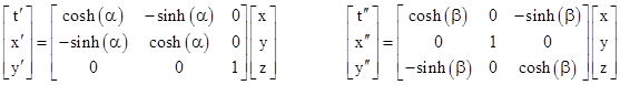
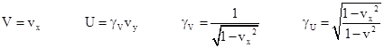
Let K, Kʹ, and Kʺ denote three systems of rectilinear inertial coordinates, denoted by t,x,y for K, by tʹ,xʹ,yʹ for Kʹ, and by tʺ,xʺ,yʺ for Kʺ. We stipulate that the origins of these systems coincide. System Kʹ has its axes aligned with those of K, and the spatial origin of Kʹ is moving with speed V in the positive x direction relative to K, so the relation between the K and Kʹ coordinates is given by the standard Lorentz transformation for a pure boost in the x direction |
|
|
|
|
|
|
|
where γV = (1−V2)−1/2 and we are using units such that c = 1. Similarly, system Kʺ has its axes aligned with those of Kʹ, and the spatial origin of Kʺ is moving with speed U in the positive yʹ direction relative to Kʹ. Therefore, the relation between the Kʹ and Kʺ coordinates is given by the standard Lorentz transformation for a pure boost in the yʹ direction |
|
|
|
|
|
|
|
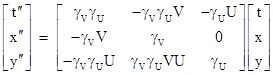
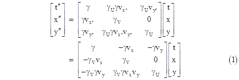
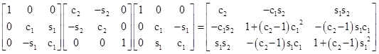
where γU = (1−U2)−1/2. The relation between K and Kʺ is simply the composition of these two transformations, i.e., we simply substitute the expressions for tʹ,xʹ,yʹ from the first transformation into the second, to give |
|
|
|
|
|
|
|
In matrix form we can write this as |
|
|
|
|
|
|
|
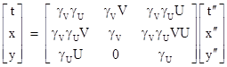
The inverse of this transformation is |
|
|
|
|
|
|
|
For the spatial origin of the Kʺ system (xʺ = yʺ = 0) we have |
|
|
|
|
|
|
|
and so the x and y components vx = dx/dt and vy = dy/dt of the velocity v of the spatial origin of Kʺ in terms of K are |
|
|
|
|
|
|
|
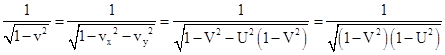
The magnitude v of the velocity vector is given by v2 = vx2 + vy2, so we have |
|
|
|
|
|
|
|
Therefore, letting γ denote (1−v2)−1/2, we have |
|
|
|
|
|
|
|
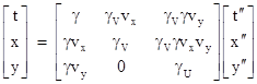
Making these substitutions, the transformation from Kʺ to K coordinates, can be written as |
|
|
|
|
|
|
|
On the other hand, the transformation from K to Kʺ implies that the xʺ and yʺ components vxʺ = dxʺ/dtʺ and vyʺ = dyʺ/dtʺ of the velocity vʺ of the spatial origin of K in terms of Kʺ are |
|
|
|
|
|
|
|
It follows that vʺ = v, as expected, but the components of vʺ are not the negatives of the components of v, as they would be in Galilean kinematics. In view of this, the transformation from K to Kʺ coordinates can be written as |
|
|
|
|
|
|
|
Given two systems of rectilinear inertial coordinates Ki and Kj, let vij denote the velocity of the spatial origin of Ki in terms of Kj. We say the coordinate systems are related by a “pure boost” if vij = −vji. As we’ve seen, the coordinate systems K and Kʺ defined above are not related by a pure boost, because the components of their relative velocities are not equal and opposite, despite the fact that the transformations from K to Kʹ and from Kʹ to Kʺ are pure boosts. |
|
|
|
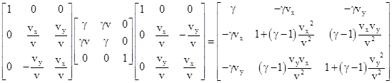
Suppose we want to define a rectilinear inertial coordinate system Jʺ that is at rest with respect to Kʺ, but that is related to the system K by a pure boost. To find such a system, we first rotate the K axes through an angle θ such that the motion of the spatial origin of Jʺ is along the new x axis. This implies vx/v = cos(θ) and vy/v = sin(θ). Then we apply the standard boost for the full speed v along the rotated x axis, and then we spatially rotate back to the original orientation. Letting r and b denote the initial rotation and the boost matrix, respectively, this overall transformation matrix is r−1br, which gives the net result |
|
|
|
|
|
|
|
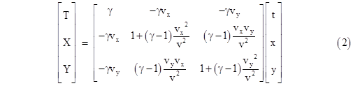
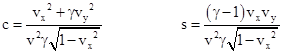
Therefore, letting T,X,Y denote rectilinear inertial coordinates of the system Jʺ, whose spatial origin is moving with components vx and vy in terms of the inertial coordinates K, we have |
|
|
|
|
|
|
|
Recalling the elementary matrix identity (MN)−1 = N−1M−1, the inverse of this transformation matrix is given by |
|
|
|
|
|
|
|
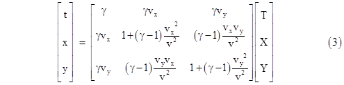
This differs from the direct transformation only in that the boost factor is inverted, which simply negates the relative velocity, so we have |
|
|
|
|
|
|
|
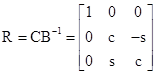
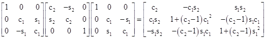
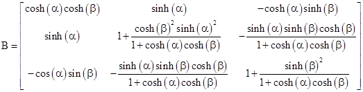
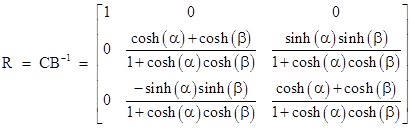
We’ve now constructed two different rectilinear inertial coordinate systems, Kʺ and Jʺ, both of which have spatial origins moving at speed v with components vx and vy in terms of K. The transformations from K to Kʺ is given by (1), and the transformation from K to Jʺ is given by the pure boost (2). Clearly Kʺ and Jʺ differ only by a spatial rotation, since their spatial origins always coincide. Letting C denote the coefficient matrix of (1), and B the coefficient matrix of (2), there is a rotation matrix R such that C = RB, and hence R = CB−1 is a pure spatial rotation, given by |
|
|
|
|
|
|
|
where |
|
|
|
|
|
In evaluating this matrix, and verifying that c2 + s2 = 1, we’ve made use of the facts that |
|
|
|
|
|
|
|
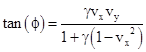
The angle ϕ of rotation produced by R is such that cos(ϕ) = c and sin(ϕ) = s, so the angle can be computed from |
|
|
|
|
|
|
|
As one would expect, the angle is zero if either vx or vy is zero, since in that case the transformation C is already a pure boost. The angle also approaches zero as γ approaches 1, which is why this re-orientation is appreciable only at relativistic speeds, i.e., when γ is significantly greater than 1. In the diagonal case, vx = vy, we have tan(ϕ) = (γ−1)/(γ+1). |
|
|
|
By the way, although we have focused on two space dimensions and one time dimension, the same reasoning that led us to equation (2) as the general boost transformation can be applied to give the general boost in three space dimensions and one time dimension: |
|
|
|
|
|
|
|
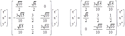
For a more concrete example of how the composition of non-colinear boosts leads to rotated coordinate systems, let us return to the case of just two space dimensions, and consider three systems of rectilinear inertial coordinates, denoted by K, Kʹ, and Kʺ, with common origins, and such that both Kʹ and Kʺ are related to K by pure boosts. Specifically, system Kʹ is purely boosted with speed vy = (1/2)√(3/2) in the positive y direction relative to K (so γ = √(8/5)), and system Kʺ is purely boosted with speed vx = vy = (1/2)√(3/2) in the “diagonal” direction relative to K (so γ = 2). Hence we have the boost relations |
|
|
|
|
|
|
|
Combining these, we get the transformation between Kʹ and Kʺ |
|
|
|
|
|
|
|
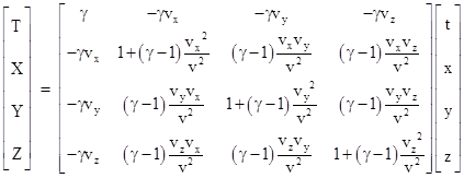
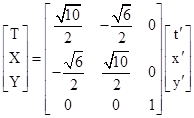
This transformation is clearly not a pure boost, as shown by the fact that dyʹ/dtʹ for the origin of the Kʺ system is 0, whereas dyʺ/dtʺ = −(1/2)√(3/5) for the origin of the Kʹ system. The pure boost from the Kʹ system to a system Jʺ of coordinates T,X,Y at rest in Kʺ is |
|
|
|
|
|
|
|
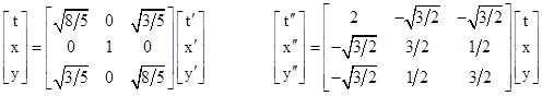
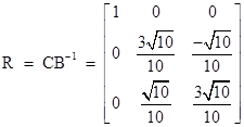
Letting C denote the coefficient matrix of the transformation from Kʹ to Kʺ, and letting B denote the pure boost from Kʹ to Jʺ, we know that there is a spatial rotation R such that C = RB. This rotation is therefore |
|
|
|
|
|
|
|
The angle ϕ of spatial rotation between Jʺ and Kʺ therefore satisfies cos(ϕ) = 3/√10 and sin(ϕ) = 1/√10, and hence tan(ϕ) = 1/3, so ϕ ≈ 18.435 degrees. This is consistent with the diagonal case of equation (4) with γ = 2. |
|
|
|
In the earlier example we specified systems such that K and Kʹ were related by a pure boost, as were Kʹ and Kʺ, and we found that K and Kʺ were not related by a pure boost. In this latest example we specified systems such that K and Kʹ were related by a pure boost, as were K and Kʺ, and we found that Kʹ and Kʺ were not related by a pure boost. In general, the composition of two non-colinear pure boosts is not a pure boost. This shouldn’t be surprising, since boosts are really just a kind of rotation in spacetime, and boosts in two different directions represent rotations about different axes. We know from everyday experience that composing rotations in non-parallel planes generally results in orientations that can be factored into rotations in completely different planes. |
|
|
|
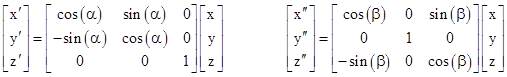
This is not unique to the spacetime kinematics of special relativity. Precisely the same thing occurs when dealing with ordinary spatial rotations in three dimensional Euclidean space (instead of spacetime with two space dimensions and one time dimension). Consider, for example, three systems of rectilinear space coordinates, K, Kʹ, and Kʺ, all with a common origin, and suppose that Kʹ and Kʺ are related to K by pure rotations in either the xz plane or the xy plane, as follows |
|
|
|
|
|
|
|
The relationship between the Kʺ and Kʹ coordinates is the composition of the right hand relation and the inverse of the left hand relation, which gives |
|
|
|
|
|
|
|
Now lets define a pure x-boost as a transformation of the form r−1br where r is a rotation in the yz plane, and b is a rotation in the xy plane. Thus an x-boost has the form |
|
|
|
|
|
|
|
where s12 + c22 = 1 and s22 + c22 = 1. The pure x-boost that matches the direction of the x axis is given by equating the top row of this matrix with the top row of (5), so we set |
|
|
|
|
|
|
|
This implies that |
|
|
|
|
|
|
|
Thus the x-boost from system K to the system Jʺ whose x axis is aligned with that of Kʺ is |
|
|
|
|
|
|
|
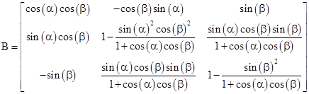
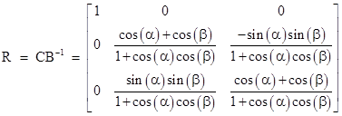
Letting C denote the coefficient matrix of (5), we see that B differs from C, which proves that Kʹ and Kʺ are not related by a pure x-boost. We need to apply some further transformation to reach Kʺ. Specifically, since B aligns the x’ and x” axes, there must be a rotation R in the yʺzʺ plane such that C = RB. This transformation is given by |
|
|
|
|
|
|
|
Thus, even though the transformation from K to Kʹ and from K to Kʺ are both pure x-boosts in the xz and xy planes, the transformation from Kʹ to Kʺ is not a pure x-boost, but it can be factored into a product of a pure x-boost and a rotation in the yʺzʺ plane through the angle ϕ given (for suitable choice of the sign of ϕ) by |
|
|
|
|
|
|
|
This is analogous to equation (4), and shows (as expected) that the angle ϕ is zero if either α or β are equal to zero. Making use of the expressions for the sine and cosine of ϕ, and basic trigonometric identities, we also have the equivalent relation between the half angles |
|
|
|
|
|
|
|
To describe the meaning of (6) in words, suppose we initially have three spatial coordinate systems, K, Kʹ, and Kʺ, all perfectly aligned with each other. Then we rotate the Kʹ system through an angle α about the z axis, and we rotate the Kʺ system through an angle β about the y axis. Now we wish to characterize the relation between the Kʹ and Kʺ axes, by imagining how we could rotate one into the other. To do this, we could apply a single rotation to the Kʹ system such that the xʹ and xʺ axes are aligned, but there are many different single rotations that would accomplish this. We choose the one that maps the Kʹ system to the Jʺ system of coordinates X,Y,Z, such that X is aligned with xʺ and the following conditions are satisfied |
|
|
|
|
|
|
|
Geometrically, this implies that an x-boost is a rotation about the line of intersection between the yʹzʹ and yʺzʺ planes. (The reverse boost from K” to K’ is the opposite rotation about the same axis, but the matrix is not simply the inverse of B, because the yʺzʺ coordinates of Kʺ are rotated relative to those of Jʺ.) These conditions are analogous to the requirement in spacetime for the components of the mutual velocity to be equal and opposite for purely boosted coordinate systems. Accordingly we could refer to this as an x-boost transformation, analogous to t-boosts in spacetime, by which we align the time axes of different systems. However, after aligning the xʹ and xʺ axes in this way, we will find that the yʹ and zʹ axes are still skewed relative to the yʺ and zʺ axes. So, to complete the re-alignment, we need to rotate the Kʹ system through an angle ϕ about the xʹ axis. For any given α and β this angle is given by equation (6). |
|
|
|
|
|
Consider, again three systems of rectilinear spacetime coordinates, K, Kʹ, and Kʺ, all with a common origin, and suppose that Kʹ and Kʺ are related to K by pure boosts (i.e., rotations in the xt and yt planes), as follows |
|
|
|
|
|
|
|
The relationship between the Kʺ and Kʹ coordinates is the composition of the right hand relation and the inverse of the left hand relation, which gives |
|
|
|
|
|
|
|
Now lets define a pure boost as a transformation of the form r−1br where r is a rotation in the xy plane, and B is a hyperbolic “rotation” in the xt plane. Thus a boost has the form |
|
|
|
|
|
|
|
where s12 + c22 = 1 and c22 − s22 = 1. (Note that c2 and s2 represent the hyperbolic cosine and sine of some suitable boost angle.) The pure boost that matches the direction of the t axis (i.e., the state of motion) of K” is given by equating the top rows of the two preceding matrices, so we set |
|
|
|
|
|
|
|
Thus the boost from system K to the system Jʺ whose state of motion matches that of Kʺ is |
|
|
|
|
|
|
|
Letting C denote the coefficient matrix of (7), we see that B differs from C, which proves that Kʹ and Kʺ are not related by a pure boost. We need to apply some further transformation to reach Kʺ. Specifically, since the “x” axes of Jʺ and K” are aligned, there must be a rotation R in the yʺzʺ plane such that C = RB. This transformation is given by |
|
|
|
|
|
|
|
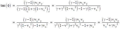
Thus, even though the transformation from K to Kʹ and from K to Kʺ are both pure boosts in the tx and ty planes, the transformation from Kʹ to Kʺ is not a pure boost, but it can be factored into a product of a pure boost and a rotation in the xʺyʺ plane through the angle ϕ given by |
|
|
|
|
|
|
|
This shows the close correspondence with the case of ordinary rotations in three-dimensional space given by equation (6). We also have the corresponding half-angle formula |
|
|
|
|
|
|
|
It may not be immediately apparent that (8) is identical to (4), but recall that |
|
|
|
|
|
|
|
where |
|
|
|
|
|
Making these substitutions into (8), and recalling that γVγU = γ, we have |
|
|
|
|
|
|
|
Multiplying the numerator and denominator by (γ – 1) gives |
|
|
|
|
|
|
|
in agreement with equation (4). |
|
|
|
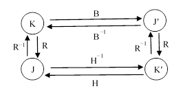
In the preceding discussion we mentioned an apparent asymmetry. In several cases we considered the transformation from one system of coordinates to another, say from K to Kʹ, represented a transformation matrix C, and we found that C could be expressed as the product RB of a pure boost B followed by a rotation R. We then computed this rotation matrix as R = CB−1. Of course, the inverse transformation is C−1 = B−1 R−1, so the boost and rotation have swapped places. But surely the situation is symmetrical, and we could just as well express the transformation from K’ back to K as a boost followed by a rotation, i.e., by the product R−1H where H is a boost. This is true, but H is not the same as the inverse of B (unless C is a pure boost), because if C = RB and C−1 = R−1H then H−1 = RBR−1. Letting Jʹ denote a system at rest in Kʹ and related to K by a pure boost B, and letting J denote a system at rest in K and related to Kʹ by a pure boost H, the relationships between the coordinate systems are depicted schematically in the figure below. |
|
|
|
|
|
|
|
In this figure, the coordinate systems K and J are in the same state of motion, so their t axes are aligned, although they differ by a spatial rotation. Likewise the coordinate systems Kʹ and Jʹ are in the same state of motion, differing only by a spatial rotation. The systems K and Jʹ are related by a pure boost, as are the systems Kʹ and J. |
|
|
|
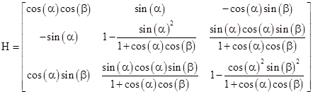
We’ve been speaking in terms of spacetime transformations and velocity boosts, but the same formal relationships apply to the purely spatial coordinate systems and our x-boosts. We simply replace the notion of being “at rest” (i.e., having the time axes aligned) with the notion of having x axes aligned. Thus the K and J coordinate systems have their x axes aligned, but differ by a rotation in the yz plane. For example, in the geometrical case we considered previously we determined the boost B and rotation R such that the transformation from K’ to K” is C = RB. For that case the boost H such that the transformation from Kʺ to Kʹ is C−1 = R−1H is given by |
|
|
|
|
|
|
|
The eigenvector of this H matrix is [0, cos(α)sin(β), sin(α)]T, whereas the eigenvector of the corresponding B matrix (given previously) is [0, sin(β), cos(β)sin(α)]T. This shows that the axis of x-boost rotation is in the yz plane of both the K’ and the K” systems, and since it is the same axis, it lies in the intersection between those two planes. These vectors refer to the same axis of x-boost rotation, merely expressed in terms of different coordinate systems. The sine and cosine of the angle of tilt between the two yz planes (i.e., the boost angle) was denoted above as c2 = cos(θb) and s2 = sin(θb), where we found that cos(θb) = cos(α)cos(β). Also, the normalized eigenvector of B can be written as [0, s1, c1] in terms of the sine and cosine parameters defined previously. |
|
|
|
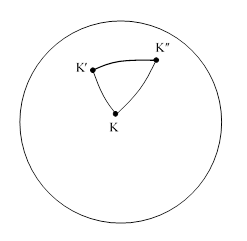
Another way of expressing these results is in terms of parallel transport. Consider three dots, denoted by K, Kʹ, Kʺ, on the surface of a sphere, with great circle arcs connecting them, as shown below. |
|
|
|
|
|
|
|
Take the point K as the origin of rectilinear xyz axes, with the x axis pointing directly outward from the surface, along the line from the center of the sphere. Now suppose we transport this coordinate system so that its origin moves along the geodesic path from K to Kʹ while keeping constant the angles of the x, y, and z axes relative to that path. This is called parallel transport. (We could transport just a single vector, but we prefer to transport an entire coordinate system.) Once we reach Kʹ we begin to transport the axes so that the origin moves along the geodesic path from Kʹ to Kʺ while keeping constant the angles of the axes relative to that path. Finally we perform a similar parallel transport of the coordinate system along the geodesic path from Kʺ to K. The origin of this system is now back where it started, and the x axis is still pointing directly upward from the surface, but the y and z axes are rotated relative to their original positions. If, for example, the angle between the geodesic paths at Kʹ is π/2, and if we let α denote the angle between the x and xʹ axis, and β denote the angle between the xʹ and xʺ axis, then the amount by which the yz axes have been rotated after making this round trip is the value of ϕ given by equation (6). |
|
|
|
In general we can imagine polygonal paths consisting of geodesic segments on the surface of a sphere, and determine the amount of angular precession that occurs when carrying a vector by parallel transport around any closed path. Applying this to the hyperbolic geometry of spacetime, the result is known as relativistic Thomas precession. |
|
|
|
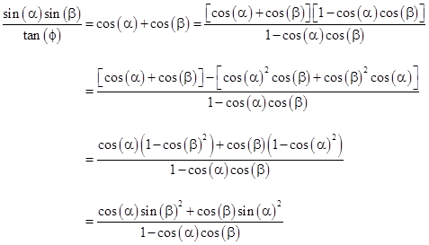
Incidentally, we can re-write equation (6) in the form |
|
|
|
|
|
|
|
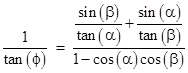
Dividing through by the product of sines, we have |
|
|
|
|
|
|
|
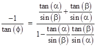
Multiplying the numerator and denominator by the product of the tangents divided by the product of the sines, and negating both sides, we get |
|
|
|
|
|
|
|
By basic trigonometric identities, the left side equals tan(ϕ + π/2), and we recognize the right side as the tangent of the sum of the arc tangents of tan(α)/sin(β) and tan(β)/sin(α). Recall from spherical trigonometry that these arc tangents are the other two angles of a right triangle on the surface of the sphere. Therefore, letting μ and ν denote these angles, we have |
|
|
|
|
|
|
|
Thus we arrive at the result |
|
|
|
|
|
|
|
We recognize the right hand side of this equation as Hariot’s expression for the area of a spherical right triangle on a sphere of unit radius. This is a special case of a theorem (Gauss) that the angle of rotation of a vector carried by parallel transport (infinitesimal geodesic segments) around any closed loop on a surface equals the integral of the intrinsic curvature C of that surface inside that loop. (The integral is taken as positive for regions surrounded by clockwise paths and negative for regions surrounded by counter-clockwise paths.) Thus the theorem asserts that |
|
|
|
|
|
|
|
The curvature of the surface of a sphere of radius R is simply the constant 1/R2, so this formula gives ϕ = A/R2 where A is the signed area enclosed by the loop, and therefore |
|
|
|
|
|
|
|
which is Harriot’s formula for the area of a spherical right triangle on a sphere of radius R. This shows that the formula for relativistic Thomas precession was, in essence, discovered by Thomas Harriot in 1603. |
|
|