|
Refraction At A Plane Boundary Between Moving Media |
|
|
|
Mathematicians usually consider the Rays of Light to be Lines reaching from the luminous Body to the Body illuminated, and the refraction of those Rays to be the bending or breaking of those lines in their passing out of one Medium into another. And thus may Rays and Refractions be considered, if Light be propagated in an instant. But by an Argument taken from the Equations of the times of the Eclipses of Jupiter's Satellites, it seems that Light is propagated in time, spending in its passage from the Sun to us about seven Minutes of time: And therefore I have chosen to define Rays and Refractions in such general terms as may agree to Light in both cases. |
|
Isaac Newton (Opticks), 1704 |
|
|
|
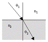
The ray angles θ1 and θ2 for incident and refracted optical rays at a plane boundary between regions of constant indices of refraction n1 and n2 are related according to Snell’s law |
|
|
|
|
|
|
|
However, this formula applies only if the media (which are assumed to have isotropic indices of refraction with respect to their rest frames) are at rest relative to each other. If the media are in relative transverse motion, it is necessary to account for the effect of aberration on the ray angles relative to the rest frames of the respective media. The result is that the effective refraction is a function of the relative transverse velocity of the media. Thus, measurements of the optical refraction could (in principle) be used to determine the velocity of a moving volume of fluid. Unlike Doppler shift measurement techniques, this approach does not rely on the presence of discrete particles in the fluid, and involves only measurements of direct, rather than reflected, light signals. |
|
|
|
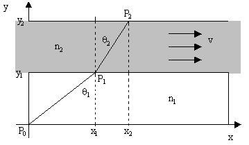
Since the amount of refraction at a boundary depends on the angle of incidence with respect to the rest frames of the media, it follows that if the media have different rest frames the simple form of Snell’s law does not apply directly, because it will be necessary to account for aberration. To derive the law of refraction for transversely moving media, consider the arrangement shown in the figure below, drawn with respect to a system of coordinates (x,y,t) relative to which the medium with refractive index n1 is at rest. |
|
|
|
|
|
|
|
In these coordinates the medium with index n2 is moving transversely with a speed v. By both Fermat’s principle of “least time” and the principles of quantum electrodynamics, we know that the path of light from point P0 to point P2 is such that the travel time is stationary (which, in this case, means minimized), so if we express the total travel time as a function of the x coordinate of the “corner point” P1, we can differentiate to find the position that minimizes the time, and from this we can infer the angles of incidence and refraction. |
|
|
|
With respect to the xyt coordinates in which the n1 medium is at rest, the squared spatial distance from P0 to P1 is x12 + y12, so the time required for light to traverse that distance is |
|
|
|
|
|
|
|
On the other hand, for the trip from point P1 to point P2 we need to know the distance traveled with respect to the coordinates x'y't' in which the n2 medium is at rest. If we define |
|
|
|
|
|
|
|
then the Lorentz transformation gives us the corresponding increments in the primed coordinates |
|
|
|
|
|
|
|
Therefore, the squared spatial and temporal distances from P1 to P2 in the n2 rest coordinates are given by |
|
|
|
|
|
|
|
|
|
|
|
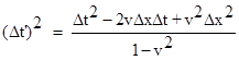
Since the ratio of these increments equals the square of the speed of light in the n2 medium, which is 1/n22, we have |
|
|
|
|
|
|
|
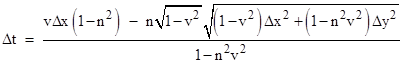
Solving this quadratic for Δt, which equals tC – tB, gives |
|
|
|
|
|
|
|
Differentiating with respect to Δx, and noting that d(Δx)/dx1 = –1, we can minimize the total travel time t2 – t0 by adding the derivatives of Δt and t1 – t0 with respect to x1, and setting the result to zero. This leads to the condition |
|
|
|
|
|
|
|
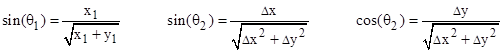
Making the substitutions |
|
|
|
|
|
|
|
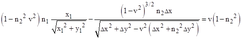
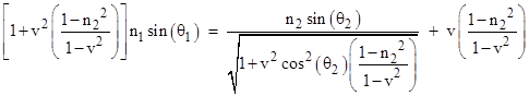
we arrive at the equation for refraction at the plane boundary between transversely moving media |
|
|
|
|
|
|
|
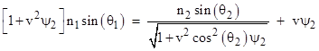
As expected, this reduces to Snell’s law for stationary media if we set v = 0. Also, if the moving medium has a refractive index of n2 = 1, this equation again reduces to Snell’s law, regardless of the velocity, because the concept of speed doesn’t apply to the vacuum. If we define the parameter |
|
|
|
|
|
|
|
then the refraction equation can be written more compactly as |
|
|
|
|
|
|
|
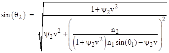
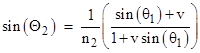
This can be solved explicitly for sin(θ2) to give the result |
|
|
|
|
|
|
|
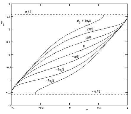
with the appropriate sign for the square root. Taking n1 = 1.2 and n2 = 1.5, the figure below shows the angle of refraction θ2 as a function of the transverse speed v of the medium with various angles of incidence θ1 ranging from –3π/8 to +3π/8 radians. |
|
|
|
|
|
|
|
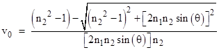
Incidentally, when plotting these lines it is necessary to take the positive root when v is above the zero-crossing speed, and the negative root when v is below. The zero-crossing speed (i.e., the speed v when the refracted angle is zero) is |
|
|
|
|
|
|
|
The figure shows that at high relative speeds and high angle of incidence we can achieve total internal reflection, even though the downstream medium is more dense than the upstream medium. The critical conditions occur when the squared quantity in parentheses in the equation for sin(θ2) reaches ±1, which implies |
|
|
|
|
|
|
|
Solving these two quadratics for v (remembering that ψ2 is a function of v), we have the four distinguished speeds |
|
|
|
|
|
|
|
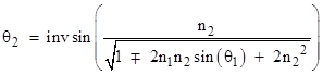
The two speeds given by ±1/n2 (which are just the speeds of light in the moving medium) generally correspond to removable singularities, because both the numerator and denominator of the expression for sin(θ2) vanish. At these speeds the values of θ2 can be assigned continuously as |
|
|
|
|
|
|
|
It isn’t clear what, if any, optical effects would appear at these two removable singularities. The other two distinguished speeds represent the onset of total internal reflection if their values fall in the range from –1 to +1. For example, the figure above shows that total internal reflection for an incident angle of θ1 = 3π/8 with n1 = 1.2 and n2 = 1.5 begins when the speed v exceeds |
|
|
|
|
|
|
|
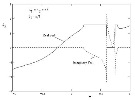
Notice that for an incidence angle of zero, this speed is simply n2, which is ordinarily greater than 1, and thus outside the range of achievable speeds (since we assume the medium itself is moving through a vacuum). However, for non-zero angles of incidence it is possible for one of these two critical speeds to lie in the achievable range. In fact, for certain values of n1, n2, and θ1, it is possible for all four of the critical speeds to lie within the achievable range, leading to some interesting phenomena. For example, with n1 = n2 = 2.5 and with θ1 = 45 degrees, the refracted angle as a function of medium speed is as shown below. |
|
|
|
|
|
|
|
In this case the distinguished speeds are –0.4, +0.203, +0.4, and +0.783. This suggests that as the transverse speed of the medium increases from 0, the refracted ray becomes steeper until reaching 90 degrees at v = +0.203, at which point there is total internal reflection. This remains the case until achieving a speed of +0.783, at which point some refraction is re-introduced, and the refracted angle sweeps back from +90 to about +80 degrees (relative to the stationary frame), and then back to +90 degrees as speed continues to increase to 1. This can be explained in terms of the variations in the effective critical angle and the aberration angle. As speed increases, the effective critical angle for total internal reflection initially increases faster than the aberration angle, pushing the ray into total internal reflection. However, eventually (at close to the speed of light) the aberration effect brings the incident ray back into the refractive range. |
|
|
|
For an alternative derivation that leads to a different, but equivalent, relation, suppose the index of refraction of the stationary region is n1 = 1, which implies this region is a vacuum. If we let d1 denote the spatial distance from P0 to P1 with respect to the rest frame, then we have |
|
|
|
|
|
|
|
These are the components of the interval P0 to P1 with respect to the rest frame of n1, and they can be converted to the frame of n2 (denoted by upper case letters) using the Lorentz transformation |
|
|
|
|
|
|
|
|
|
|
|
|
|
|
|
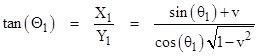
For convenience we have reversed the sense of v from the previous discussion. Letting Θ1 denote the angle θ1 with respect to the moving n2 coordinate system, we can express the tangent of this angle as |
|
|
|
|
|
|
|
Taking the sine of the inverse tangent of both sides gives the familiar aberration formula |
|
|
|
|
|
|
|
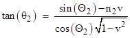
Since we are assuming the n1 medium is a vacuum, we are free to treat the entire configuration as being at rest in the n2 coordinates, with the angle of incidence as defined above. Therefore, Snell’s law for stationary media can be applied to give the refracted angle relative to these coordinates |
|
|
|
|
|
|
|
Now, if D2 is the spatial distance from P1 to P2 with respect to the moving coordinates, we have |
|
|
|
|
|
|
|
Also, the Lorentz transformation gives the coordinates of points P1 and P2 in the rest frame in terms of the coordinates in the moving frame as follows: |
|
|
|
|
|
|
|
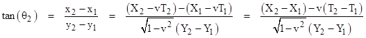
From these we can construct the tangent of θ2 with respect to the rest coordinates |
|
|
|
|
|
|
|
Substituting for the coordinate differences gives |
|
|
|
|
|
|
|
We saw previously that |
|
|
|
|
|
|
|
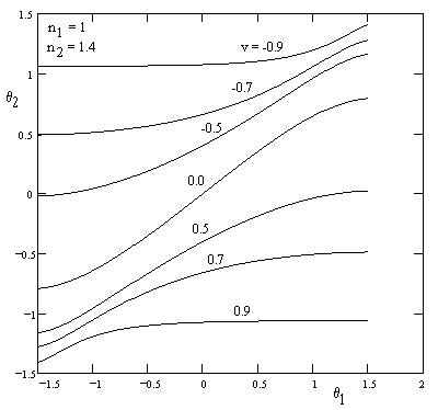
so we can explicitly compute θ2 from θ1. It can be shown that this solution is identical to the solution (with n1 = 1) derived previously on the basis of Fermat's principle (noting that we here defined v as the speed of the n1 medium relative to the n2 medium, so the sign of v is reversed from the previous formula). Furthermore, we can solve these equations for sin(θ1) as a function of θ2 and then by equating this sin(θ1) with n3 sin(θ3) for a stationary medium neighboring the vacuum region, we again have the general solution for two refractive media in relative transverse motion. A plot of θ2 from θ1 for various values of v is shown below: |
|
|
|
|
|
|