|
5.1 Vis Inertiae |
|
|
|
It is indeed a matter of great difficulty to discover, and effectively to distinguish, the true motions of particular bodies from the apparent, because the parts of that immovable space in which those motions are performed do by no means come under the observation of our senses. Yet the thing is not altogether desperate… |
|
Isaac Newton, 1687 |
|
|
|
According to Newtonian mechanics a particle moves without acceleration unless acted upon by a force, in which case the particle undergoes acceleration proportional to the applied force. The acceleration is defined as a vector whose components are the second derivatives of the particle’s space coordinates with respect to the time coordinate, which would seem to imply that the acceleration of a particle – and hence the force to which the particle is subjected – depends on our choice of coordinate systems. Of course, Newton’s law is understood to be applicable only with respect to a special class of coordinate systems, called the inertial coordinate systems, which all give the same acceleration, and hence the same applied force, for any given particle. Thus the restriction to inertial coordinate systems enables us to regard accelerations and the corresponding forces as absolute. |
|
|
|
However, even in the context of Newtonian mechanics it is sometimes convenient to set aside the restriction to inertial coordinate systems, and as a result the distinction between physical forces and coordinate-based accelerations becomes ambiguous. For example, consider a particle whose position in space is expressed by the vector |
|
|
|
|
|
|
|
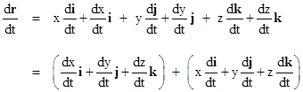
where i, j, k are orthogonal unit vectors for a coordinate system with fixed origin, and x(t), y(t), z(t) are scalar functions of the time coordinate t. Obviously if these basis vectors are unchanging, the derivatives of r are simply given by |
|
|
|
|
|
|
|
but if the basis vectors may be changing with time (due to rotation of the coordinate axes) the first derivative of r by the chain rule is |
|
|
|
|
|
|
|
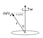
The quantity in the first parentheses is the partial derivative of r with respect to t at constant basis vectors i, j, k, so we denote it as ∂r/∂t. The quantity in the second parentheses is the partial derivative of r with respect to t at constant x, y, z, which means it represents the differential change in r due just to the rotation of the axes. This change is perpendicular to both r and the angular velocity vector ω, and its magnitude is ωr times the sine of the angle between ω and r, as indicated in the figure below. |
|
|
|
|
|
|
|
Therefore, the total derivative of r with respect to t can be written as |
|
|
|
|
|
|
|
Notice that this applies to any vector (compare with equation 4b in Appendix 4, noting that the angular velocity serves here as the “Christoffel symbol”), so we can immediately differentiating again with respect to t, giving the total acceleration |
|
|
|
|
|
|
|
Noting that the cross product is distributive, and that the chain rule applies to derivatives of cross products, this can be written as |
|
|
|
|
|
|
|
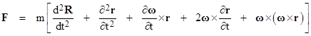
This was based on the premise that the origin of the x,y,z coordinates was stationary, but if we stipulate that the origin is at position R(t) with respect to some fully inertial coordinate system, then the particle’s position in terms of these inertial coordinates is R+r and the total acceleration of the particle includes the second derivative of R. Thus Newton’s second law, which equate the net applied force F to the mass times the acceleration (defined in terms of an inertial coordinate system), is |
|
|
|
|
|
|
|
If our original xyz coordinate system was inertial, then all the terms on the right hand side except for the second would vanish, and we would have the more familiar-looking expression |
|
|
|
|
|
|
|
Now, if we are determined to organize our experience based on this simple formulation, for any arbitrary choice of coordinate systems, we can do so, but only by introducing new “forces”. We need only bring the other four terms from the right hand side of the previous equation over to the left side, and call them “forces”. Thus we define the net force on the particle to be |
|
|
|
|
|
|
|
The first term on the right side is the net of the “physical forces”, whereas the remaining terms are what we might call “inertial forces”. They are also often called “fictitious forces”. The second term is the linear acceleration force, such as we may imagine is pulling us downward when standing in an elevator that is accelerating upward. The fourth term is called the Coriolis force, and the fifth term is sometimes called the centrifugal force. (The third term apparently doesn’t have a common name, perhaps because the angular velocity in many practical circumstances is constant.) On this basis the Newtonian equation of motion in terms of an arbitrary Cartesian coordinate system has the simple form |
|
|
|
|
|
|
|
It’s interesting to consider why we usually don’t adopt this point of view. It certainly gives a simpler general equation of motion, but at the expense of introducing several new “forces”, beyond whatever physical forces we had already identified in F. Our preference for the usual (more complicated or more restrictive) formulation of Newton’s law is due to our desire to associate “physical forces” with some proximate substantial entity. For example, the force of gravity is attributed to the pull of some massive body. The force of the wind is attributed to the impulse of air molecules. And so on. The “inertial forces” can’t be so easily attributed to any proximate entity, so unless we want to pursue the Machian idea of associating them with the changing relations to distant objects in the universe, we are left with a “force” that has no causative substance, so we tend to regard such forces as fictitious. Nevertheless, it’s worth remembering that the distinction between “physical” and “fictitious” forces is to some extent a matter of choice, as is our preference for inertial coordinate systems to measure time and space. |
|
|
|
To illustrate some of the consequences of these ideas, recall that the Sagnac effect was described in Section 2.7 from the standpoint of various systems of inertial coordinates, and in Section 4.8 in terms of certain non-inertial coordinate systems, but in all these cases the analyses was based on the premise that the “true” measures of time and space were based on inertial coordinate systems. We can now examine some aspects of a Sagnac device from a more general standpoint of arbitrary curvilinear coordinates, leading to the idea that the “physical” effects of acceleration can be absorbed into the metrical structure of spacetime itself. |
|
|
|
In a square or triangular Sagnac device the light ray going from one mirror to the next in the direction of rotation passes through the interior of the polygon when viewed from a non-rotating frame of reference. This implies that the light ray, traveling in a straight line, diverges from the rim of the Sagnac device and then converges back to the next vertex. On the other hand, if we consider the same passage of light from the standpoint of an observer riding along on the rotating device, the beam of light goes from one end of the straight edge to the other, but since the light beam diverges from the edge and passes through the interior of the polygon, it follows that from the standpoint of the rotating observer the ray of light is emitted from one vertex and curves in toward the center of rotation and then curves back to reach the next mirror. Likewise, the counter-rotating ray travels outside the polygon, so when viewed from the rotating frame it appears to curve outward (away from the center) and then back. |
|
|
|
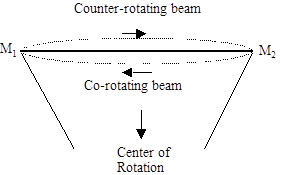
So, on a typical segment between two mirrors M1 and M2, when viewed from the rotating frame of reference, the two light rays follow curved paths as shown in the drawing below: |
|
|
|
|
|
|
|
The amount of this "warping" of the light rays depends mainly on the shape of the path and the speed of the rim, so if we have significant warping of light rays with small r, the warping won't be reduced by increasing the radius while holding the mirror speed constant. Any bending of light rays would reveal to an observer that the segment M1 to M2 is not inertial, so if we want to construct a scenario in which an observer sitting on a mirror is "inertial for all practical purposes", we need to make each segment subtend a very small arc of the disk and/or limit the rim speed, as well as restricting our attention to a short enough span of time so that the rotating observer doesn't rotate through an appreciable angle. |
|
|
|
One thing that sometimes misleads people when assessing how things look from the perspective of a rim observer is that they believe it was only necessary to consider the centripetal acceleration, v2/R, of each point on the rim, but clearly if our objective is to assess the speed of light with respect to a coordinate system in which an observer at a particular point on the rim is stationary, we must determine the full accelerations of the points on the rim relative to that system of coordinates. This includes the full five-term expression for the acceleration of a moving point relative to an arbitrarily moving coordinate system. On that basis we find that the light rays are subjected to an "acceleration" field whose dominant term has a magnitude in the direction of travel of |
|
|
|
|
|
|
|
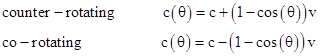
where θ is the angular distance from the observer. (Note that this acceleration is defined on the basis of "slow-measuring-rod- transport" lengths around the loop, combined with time intervals corresponding to the rim observer's co-moving inertial frame. Also, note that "vc/R" is characteristic of the Coriolis term, as opposed to v2/R for the centripetal term.) Integrating these accelerations in both directions gives the pseudo-speeds (i.e., the speeds relative to the accelerating coordinates) of the two light beams as a function of position in the acceleration field |
|
|
|
|
|
|
|
The average pseudo-speeds of the co- and counter-rotating beams around the loop are therefore c-v and c+v respectively, which gives a constant "anisotropic ratio". However, these speeds differ from c at any particular point only in proportion to the pseudo-gravitational potential relative to the observer's location. The amplitude of the acceleration field averaging cv/R does indeed go to zero as the radius R increases while holding the rim speed v constant, but the integral of ±(cv/R)sin(θ) over the entire loop still always gives the speed distribution around the rim noted above, with the maximum anisotropy occurring at the opposite point on the circumference (where the pseudo-gravitational potential difference relative to the observer is greatest), and this gives the constant "anisotropic ratio". All of this is in perfect accord with the principles of relativity. |
|
|
|
Of course, if the problem is treated in terms of inertial coordinates, then acceleration isn't an issue, and the solution is purely kinematical. However, our purpose here is to examine the consequences of re-casting the Sagnac effect into a system of non-inertial coordinates in which an observer sitting on the rim is stationary, which means we need to absorb into the coordinates not only his circular translatory motion but also his rotation. This introduces fictitious forces and acceleration/gravitational fields which must be taken into account. Needless to say, there's no need to go to all this trouble, since the treatment in an inertial frame is completely satisfactory. The only reason for re-casting this in non-inertial coordinates is to illustrate how the general relativistic theory accommodates the use of arbitrary coordinates. |
|
|
|
Now, it's certainly true that there is no single coherent set of coordinates with respect to which all the points on the disk are fully stationary, where the term "coherent" signifies a single unique locus of inertial simultaneity. We can, however, construct a coherent set of coordinates with respect to which one particular point on the rim is fully stationary, and then use slow-transport methods for assigning spatial distances between any two mirrors, and combine this with the observer's proper time as the basis for defining velocities, accelerations, etc, with respect to the rim observer's accelerating coordinates. |
|
|
|
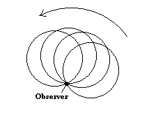
To understand the nature of the pseudo-gravitational fields that exist with respect to these accelerating coordinates, carry out the transformation to the observer's system in two steps. First, construct a non-rotating system of coordinates in which the observer is constantly at the origin. Thus we have absorbed his circular motion but not his rotation into these coordinates. The result is illustrated below, where the disk is regarded as rotating about the "stationary" observer riding on the rim, and the circles represent the disk position at different "times" (relative to these coordinates). |
|
|
|
|
|
So, at this stage, each point on the disk is twirling around the observer at an angular speed of w (the same as the speed of the disk in the hub-centered coordinates). If we draw the spiro-graph traced out by a point moving around the circle at speed c while the circle rotates slightly about the observer with angular speed w = v/R, we see that the co-and counter-rotating directions have different path lengths, precisely accounting for the difference in travel times. Thus, even with respect to these accelerating coordinates (in which the observer has a fixed position), the Sagnac effect is still due strictly to the difference in path length, which demonstrates how directly the Sagnac effect is due not just to acceleration in general but specifically to rotation. |
|
|
|
Next, we absorb the rotation of the disk into our coordinates, so the disk is no longer twirling around the observer. However, by absorbing the twirl of the disk into the coordinates, we introduce an anisotropic pseudo-gravitational field (relative to the "stationary" observer), for particles or light rays moving around the loop. The fact that the "speed of light" in these coordinates can differ from c is exactly analogous to how the distant stars have enormous speeds with respect to the Earth's rotating coordinates, and that speed is attributed to the enormous pseudo-gravitational potential which exists at those distances with respect to the Earth's coordinates. Similarly, relative to our rim observer, the maximum gravitational potential difference is at the furthest point on the circle, i.e., the point diametrically opposite on the disk, which is also where the greatest anisotropy in the "speed of light" (with respect to these particular non-inertial coordinates) occurs. |
|
|
|
Thus, to first order with relatively small mirror speeds, the light rays are subjected to an "acceleration" field whose magnitude in the directions of travel is ±(vc/R)sin(θ) where θ is the angular distance from the observer. Now, it might seem that we are unable to account for the anisotropic effect of acceleration, on the assumption that all the points on the rim are subject to the same acceleration, so there can be no differential effect for light rays moving in opposite directions around the loop. However, that's not the case, for two reasons. First, the acceleration (with respect to these accelerating coordinates) is not constant, and second it is the Coriolis (not the centripetal) acceleration that produces the dominant effect. The Coriolis acceleration is the cross product of the rotation (pseudo) vector w with the velocity vector of the object in question, and this has an opposite sense depending on whether the object (or light ray) is moving in the co-rotating or counter-rotating direction. |
|
|
|
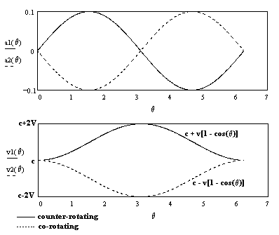
Of course, both directions eventually encounter the same amount of positive and negative acceleration, but in the opposite order. Thus, they both start out at c, and one experiences an increase in velocity of +v followed by a decrease of –v, whereas the other drops down by –v first and then increases by +v. Thus their accelerations and velocities as functions of angular position are as shown below: |
|
|
|
|
|
|
|
The average speeds of the co- and counter-rotating beams around the loop are therefore c-v and c+v respectively, which gives the constant "anisotropic ratio". Notice that the speeds differ from c only where there is significant pseudo-gravitational potential relative to the observer's location (just as with the distant stars, and of course the relation is reciprocal). The intensity of the acceleration field is on the order of cv/R, which does indeed go to zero as the radius R increases while holding the rim speed v constant, but the integral of ±(cv/R)sin(θ) over the entire loop still always gives the speed distribution around the rim noted above, with the maximum anisotropy occurring at the opposite point on the circumference (where the pseudo-gravitational potential difference relative to the observer is greatest), and this gives the constant "anisotropic ratio". |
|
|
|
It's also worth noting that the anisotropic ratio of speeds given by this pseudo-gravitational potential corresponds precisely to the anisotropic distances when the Sagnac device is analyzed with respect to the instantaneously co-moving inertial frame of the rim observer. |
|
|